
From Larkspur to Clansman Part 5b in a series of articles by G8DXU
This instalment has now been updated from issue 5a to 5b and continues the series with some general notes on the PRC320 (UK/RT320). Information is provided on servicing and some of the most common problems encountered. RT320 Transceivers cover 1.9-29.999MHz with CW, AM, and SSB modes. Probably being the most popular Clansman HF portable amongst radio amateurs. These notes are intended as a guide to the areas that may require attention rather than a definite guide to repair.
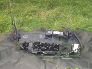
Clansman RT320 (PRC320)
General construction & Units
In common with all of the Clansman series radios the RT320 is of robust construction. The circuitry being contained within a sturdy die-cast aluminium housing which is sealed with gaskets at the front and rear panel. All rotating controls are sealed with “O” rings with similar seals around all other entries. The RT320 is also pressurised with dry air at about 4psi. Immersing the unit in water and checking for bubbles revealing any leaks.
Both the front and rear panels are retained to the main body with fourteen 3mm Hexagonal Key bolts. Before opening the case it is customary to unscrew and remove the decissator or pressurisation screw on the main body to relieve any internal air pressure.
The rear panel contains the Transmitter RF amplifier, driver tuning and Audio Interface circuitry. And is connected to the main unit (& front panel) by a special “D” Type plug and socket which also carries the associated coaxial connections. This whole unit can be pulled free of the case as required. Fortunately the rear units rarely present with any faults and only have to be removed when testing the main unit out of its case.
The front unit
This contains the main tuning, frequency generation and signal processing circuitry together with the Aerial Tuning Unit (ATU).
The Rear Unit
Contains RF Power amplifier, External aerial connections and Audio interface.
Preventative Maintenance
RT320s were first in volume production around 1976 and some may now be well over 40 years old. During service they would have been regularly tested and serviced by the REME.
The REME would have used special to type field test equipment and manufacturers replacement units. This is necessary to keep the relatively complex unit in fully functional condition and ensure that it will not fail when needed to pass a vital message.
As far as the MOD is concerned when the equipment was reaching the end of its service life, some items may not have received such special attention towards the time of disposal. There is also evidence of units being repaired by contractors, where the standards of work were not as high.
Generally all Clansman sets were maintained to a very high standard but be cautious of radios released via surplus dealers, which are often sold as untested and may sometimes be internally damaged or incomplete.
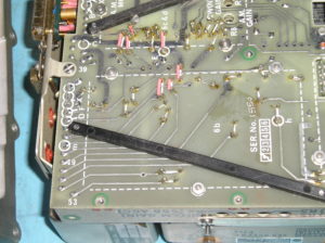
Routine Servicing
One important area of attention is to ensure that internal nuts and bolts are tight and have not worked loose. Check the tightness of all visible nuts and bolts; the bolts retaining the range switch turret assembly to the front panel require particular attention. Also the cover on the range switch needs to be removed to access the individual range wafers. The bolts retaining each of the wafers to the drum should be checked for tightness.
During this procedure and when operating the RT320 it is important to only rotate the Range Switch in a Clockwise direction. The helps prevent damage to the switch contacts by rotating in the same direction as the natural profile of the contact cam.
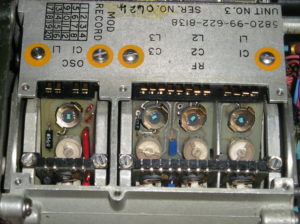
Turret assembly Range wafer contacts and securing bolts (Cover removed)
Loose wafer bolts can cause instability of the PLL particularly on the upper ranges.
Servicing the PLL Module
Tantalum Capacitors in PLL Ramp Generator
Note green corrosion products on right hand end of lead.
In part two of these articles it was mentioned that some units employed special High Voltage Tantalum Capacitors. Tantalum capacitors were relatively new in the 1970s and represented a major advance in capacitor technology. The Wet Tantalum allowed capacitors to be constructed with a high capacitance to volume ratio, low Electronic Series Resistance (ESR) and good stability. This made them ideal for use in power supplies and coupling or decoupling applications. Most Tantalum capacitors have relatively low working voltages when compared to electrolytic types. The power supply in the RT320 has an output of 110V for the PLL and Vari-Cap tuning. This required the Plessey designers to use specially manufactured Tantalum capacitors that are now very difficult to source.
After the passage of thirty or so years the leakage from many of these capacitors has increased, lowering the 110V output or causing complete failure of this part of the PSU module. Often the increased load caused by failing capacitors overloads the series stabiliser transistors, which break down.
One of the first things that experienced service engineers look for in faulty equipment of 1970s manufacture is short circuit Tantalum Capacitors! They are the cause of many failures in power supplies and often fail short-circuit or burn out with obvious signs.
The capacitors in question are C2 and C3 in the Ramp Generator Module. These are 9uF at 125V
They can be replaced with two 22uF 63V items in series making 11uF at 126V. The capacitors can be soldered together and sleeved with heat-shrink. The physical size is then such that they will easily fit in the original positions.
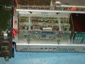
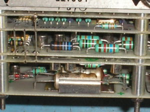
PLL Module 9 Cover removed showing Ramp Generator
Cover Nuts & bracket removed (This is the outermost board)
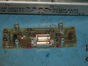
Ramp Generator PEC, removed ready for repair.
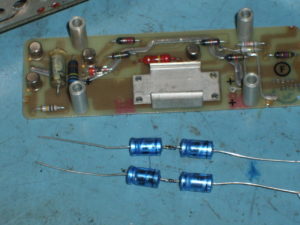
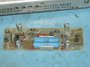
New Capacitors awaiting installation Replacement Capacitors covered with Heat Shrink & soldered in position.
Servicing The Power Supply Module (Unit No.5)
When the set is switched on a 2kHz tone should be heard from the handset or headset, this indicates that the PLL has not locked and normally stops when the correct range switch setting is selected.
In faulty sets this warning tone is often continuous and usually indicates failure of the Power Supply 110V line, PLL module or perhaps switch contacts in the Turret assembly..
When encountering a faulty RT320 the first port of call is the Power Supply module.
Remove the top case of the module and check that there is around 121V at checkpoint (TP2) on board 5b. Also test the voltage at the output of the series stabiliser is about 110V.
This tuning voltage supply is dependant upon the nominal 12V supply, which should be checked and set correctly as required.
There are actually five supplies in Module 5 these are nominally 3V, 6V, 6V Osc., 12V and 110V
If required adjust variable resistors as shown to obtain the correct output voltage limits.
PEC Board Adjust Pre-Set Nominal Voltage Limits
5a R3 12V Supply for 121.370-120.630V at TP2
5a Check 12V Supply Output 13.130-12.070V
5a R7 2.9V (3V) 2.901-2.898V
5b R4 6V 6.019-5.981V
5b Check 6V Osc. O/P +/- 0.01V of above
5b R11 110V 110.170-109.830V
The Test Kit Power supply (described later) allows these voltages to be properly checked under load or dynamic conditions.
Common failures are often due to problems with the 110V tuning supply, frequently caused by leaky Tantalum capacitors as mentioned previously. There is a custom Plessey CN587T (ML1) Integrated Circuit that produces Pulse Width Modulation at around 40kHz to drive a BC107 (CV10440) transistor (TR3). This is connected to a Ferrite Pot Core transformer to produce around 122V. If there is no output from TR3 into the bridge rectifier, check this transistor for failure of the B-E junction and replace as required.
The 110V DC is obtained by a series voltage stabilizer, of which high voltage transistors TR6 & TR7 (FRB700 / BSV29) on board 5b form part. Suitable replacement transistors for these are the MPSA42. Other devices in this circuit are TR4, CV7648 / BSY95A, and TR5, 2N5401.
Please see EMER 640/HA/09593 for detailed information.
Further detail on repair is beyond the scope of this article but may follow in future notes should there be sufficient feedback from readers.
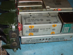
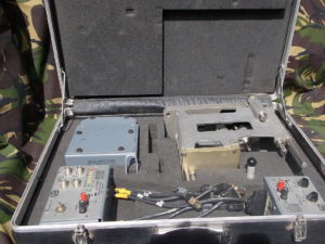
Test Kit Radio RT320
This is an essential kit for those undertaking regular service works on the RT320.
The complete kit is contained in suitcase under reference NSN 6625-99-622-5100 and comprises the following items:-
TEST SET RADIO NSN 6625-99-622-5389
TEST SET POWER SUPPLY NSN-6625-99-622-5390
STAND ASSEMBLY NSN 6625-99-622-5391
SHIELD TERMINAL BOARD NSN-5940-99-637-0511
ALIGNMENT JIG REAR PANEL NSN-6625-99-630-6101
Probe Assy 640/1/15472 NSN 6625-99-637-0512
Extractor NSN-5120-99-630-6190
Extractor ITT Cannon CET-C6B
Test Set Radio facilitates separation of the RT320 Front and Rear units’ whist providing test access points for measurements.
Test Set Power Supply allows output voltages of the PSU, (Unit 5) to be checked under load conditions.
The Stand Assembly and Shield Terminal Board are of assistance when making measurements on the main assembly PEC. Alignment Jig Rear Panel being used to check that the Front and Rear panel connectors are correctly aligned. Adjustments can be made prior to final assembly without risking damage to the special “D Type” connector contacts.
Main Sub Assembly PEC
The main Printed Electronic Circuit (PEC) carries the four modules of which 6b contains the detectors for AM & SSB, signal processing, AF signal switching and the audio output stage. Problems can occur when units have been subjected to mechanical impacts during service. Tantalum capacitors are relatively heavy, with mechanical shocks causing these to develop poor connections with the sub assembly PEC. Poor connections on C27 or C28 on Unit 6b have been found to cause low audio output on receive.
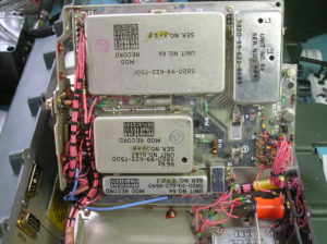
Internal PEC, securing screws removed and assembly lifted for access to modules.
Barry G8DXU
copyright 16.12.2018
Notes
REME = Radio Electrical and Mechanical Engineers
PEC = Printed Electronic Circuit
When this equipment was first produced it formed part of the worlds most advanced military radio communications system. It employs custom made Integrated circuits and some surface mount technology. When properly serviced and adjusted the PRC320 can still give performance that equals some of the best modern radios. Maintaining this performance requires some very good test equipment.
Also proper maintenance and repair requires skills that are really only developed by those that have undergone training by government or commercial organisations. If you do not have the appropriate equipment or skills you are directed to entrust repairs to those amateurs or commercial operations that can carry out such work to the appropriate standards.