
The Clansman VRC353 vehicular or Fixed station Transceiver covers 30-75.975Mhz with an output power of circa 50W. This radio can be used for re-broadcast when associated with the RB2 or similar harness interface. NATO radios have an embedded 150Hz tone similar to CTCSS which triggers the re-broadcast function. In Clansman equipment this tone is filtered out so that the operator is not aware of its presence.
When set to Narrow, the main deviation is about 6kHz which is acceptable for amateur 4m or 6m frequencies with 25kHz channel separation. However the Tone deviation is set at about 1.6kHz which is much higher than the normal 10-20% of system deviation. Amateurs using Clansman or most converted PMR sets will enjoy filtering of frequencies below 300Hz. Others will hear an, perhaps annoying 150Hz buzz!
Fortunately turning off the tone produced by the VRC353 is a relatively easy process. The Silica Gell Dessicator at the rear of the outer case should be unscrewed first. This releases any difference in air pressure between the internal hermetically sealed case and local atmosphere. Next remove the four Hex bolts in each of the front corners of the case. Now release the Hex bolt between the two cooling fans.
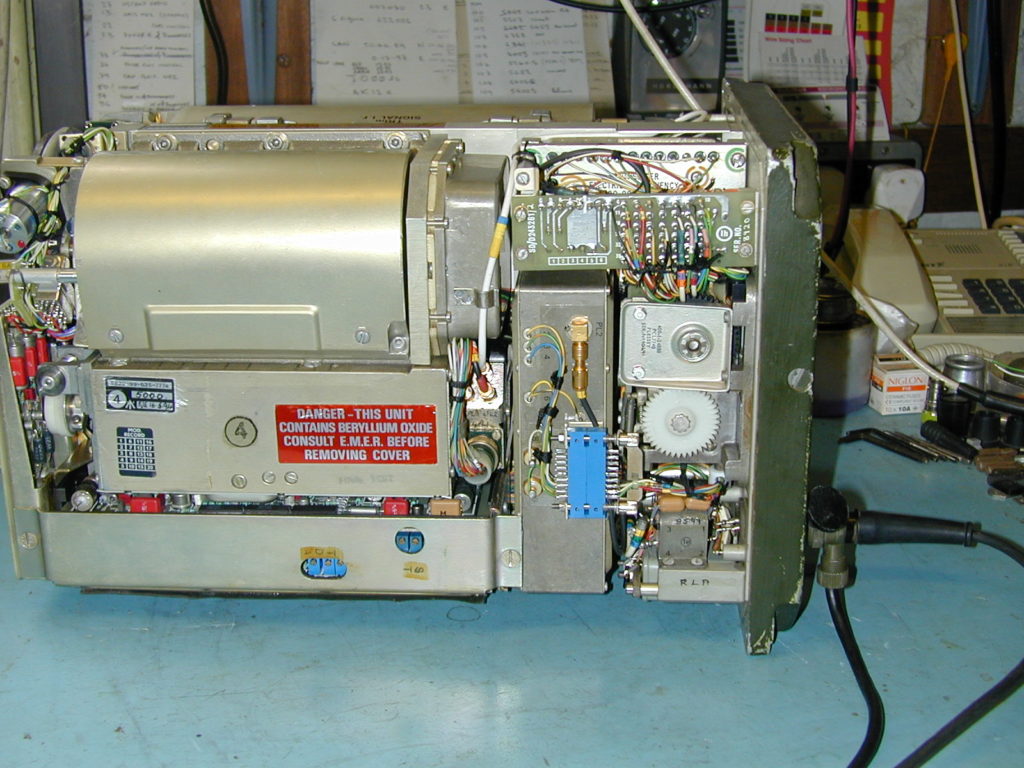
Using the handle on the front of the transceiver gently pull the body out of the case. Be careful as the outer case and main unit are both quite heavy. Once withdrawn, lay the unit on a protective and ideally, grounded static conductive matting as pictured below.
On the lower left hand side of the radio (viewed from the front) is found a group of four control boards. Printed Electronic Circuits (PEC’s) These boards number from the bottom and it is No.2b that contains the Transmitter Deviation controls. There is a plate retaining the PECs held in place by two fasteners. It is not necessary to remove this plate or any board.
Adjustments should be made through the slot in the plate where each Multi-Turn Potentiometer is readily accessible. These controls are labelled A, D & T from left to right.
“A” adjusts the Main or Analogue deviation. “D” adjusts the Data Deviation and “T” (R2) the Tone deviation. Do not touch the Analogue of Data deviation controls unless you have access to a good deviation meter and audio signal source!
The transceiver should be tested before and after adjustments to ensure that it is functioning correctly. Please do not carry out any adjustments unless you are competent with working on such complex equipment. Also bear in mind that these radios are were first produced in 1977 and suffer from the usual component ageing, making their future reliability increasingly uncertain. Repairs require special to type test equipment that may not be available to most radio amateurs.
However properly maintained VRC353s are generally quite reliable and capable of some very good performance when used on FM (Narrow) in the Four and Six metre amateur bands.
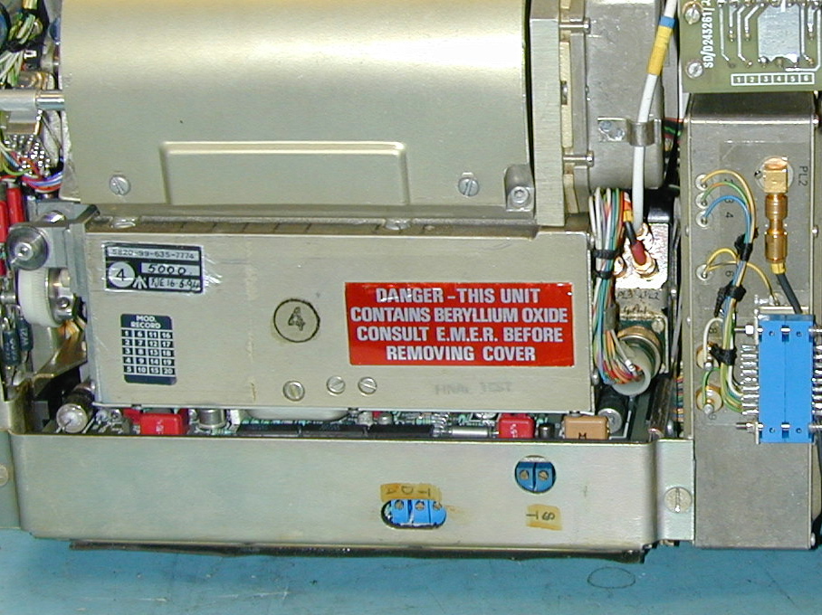
Above photograph shows details to locate the Deviation adjustments. The three presets are visible through the slot in the Control Board cover. Tone level is by the right hand control labelled “T”
When reassembling the unit and replacing the outer case ensure that this is done in dry warm conditions. Apply a smear of general purpose grease around the front panel “O” ring seal, then replace and tighten the Hex bolts. Lastly the perforated aluminium tube containing the dessicant should be unscrewed from its retaining window. Dry this in an Oven at around 100 degrees C before reassembly and return it to its original position in the case.
The note regarding Beryllium Oxide refers to the Transmitter Output valve and is only a hazard to health if damaged or tampered with.
Barry G8DXU Copyright 25.10.20