
This instalment continues the series with a look at vehicle harness systems and Rebroadcast operation in more detail.
Clansman Fixed Harness System
The harness has the following prime functions: –
- PTT control and Audio path to selected radios for access to radio nets.
- Intercommunications between vehicle crewmembers and remote operators.
- Control of rebroadcast facilities.
- Connection of accessories, Loudspeakers, Data Terminals, Encryption etc.
Harness systems are not a new development and have certainly existed since the Wireless Sets No.19 introduced in 1941.
The harness and general control system has been gradually refined since these times with the Larkspur harness (c1955) representing a major step forward. The vastly superior connectors (Plessey MkIV) employed, together with Waterproof enclosures being just two of the improvements.
Principally the main aim of the harness is to facilitate intercommunications and operation of the radio sets from several different positions. In an armoured fighting vehicle (AFV) the Driver, Crew and Commander would each have access to a box linked on the radio.
In the noisy environment of an AFV it is essential that the vehicle commander can pass orders to those under his or her command. Also each crewmember must be able to talk back to the commander and others using the Intercom. Headsets with noise cancelling features are used in particularly noisy situations.
Each vehicle is fitted with harness boxes according to operational requirements and the
level of system control required or attributed to a particular location. Live access to radio nets depend upon the switch settings of the various boxes serving each harness location.
Principal settings being “I” Intercom “A” Radio system (Perhaps VHF) or “B” radio system (Perhaps HF). There is usually a momentary switch position labelled “C” Call, which injects a tone over the Intercom to attract attention. This is especially useful for remote operation where operators are nearby, but not continuously monitoring.
Ultimately access to the radio system via the harness or remote control is set at the radios
to which the harness is connected. Vehicle radios such as the RT321 and RT353 have a switch labelled REMOTE. When this is in the LOCAL position, only the local operator can key the transmitter with the PTT and speak over the air. Access to the radio from harness positions is blocked whilst under local control. However the intercom between crew positions continues to function independent of radio settings.
The RT353 also has a provision for Automatic Rebroadcast labelled “AUTO” this is used when two or more VHF sets are interconnected via the appropriate control box.
Harness systems vary from as little as one or two boxes in a lightweight vehicle to many on the larger armoured vehicles. The IB2 or IB3 units are the starting point for most installations where only two or three radios require interconnection.
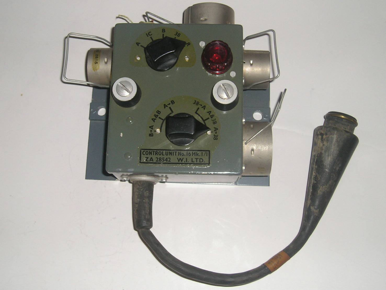
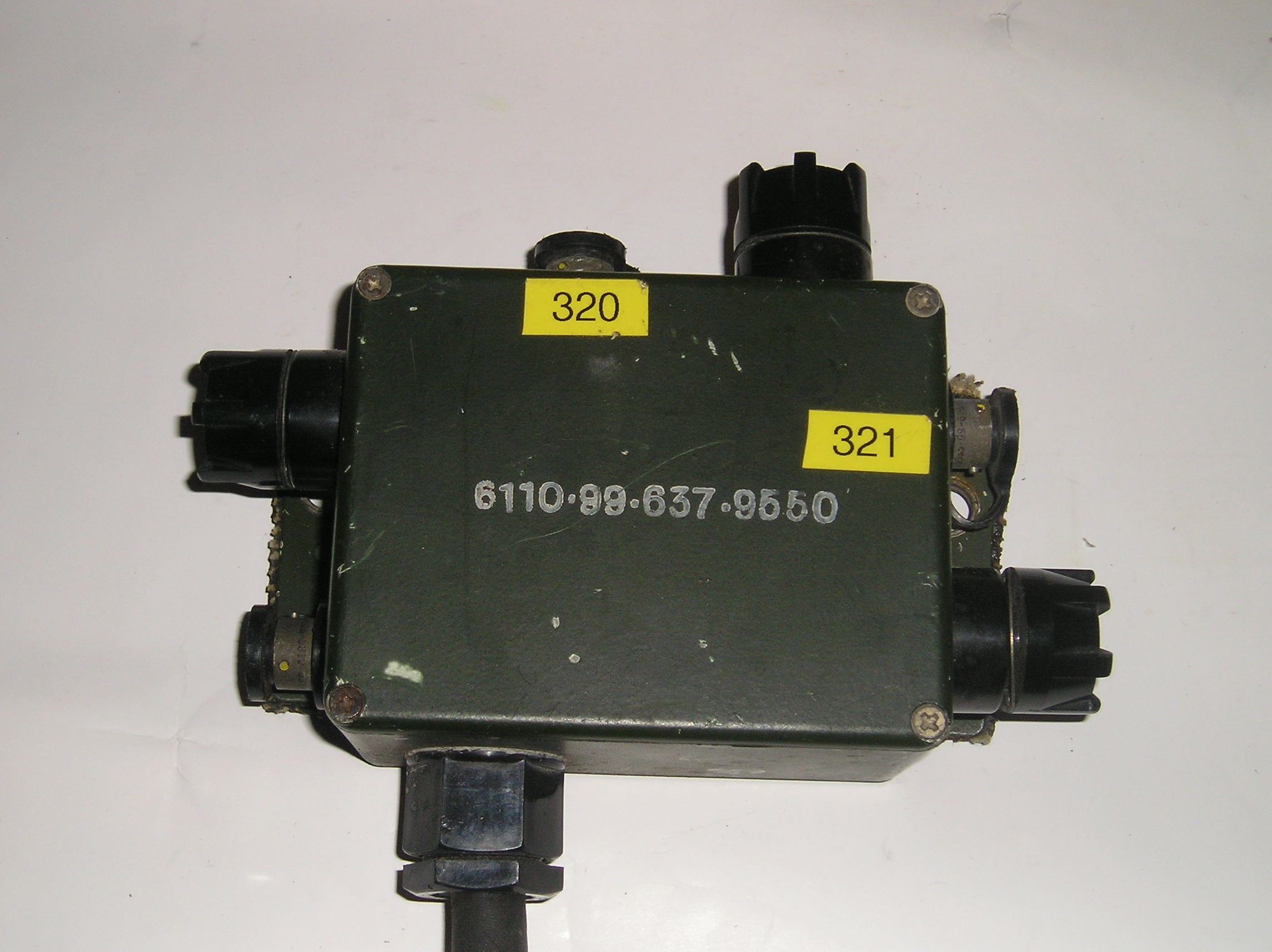
Interconnecting Box 2
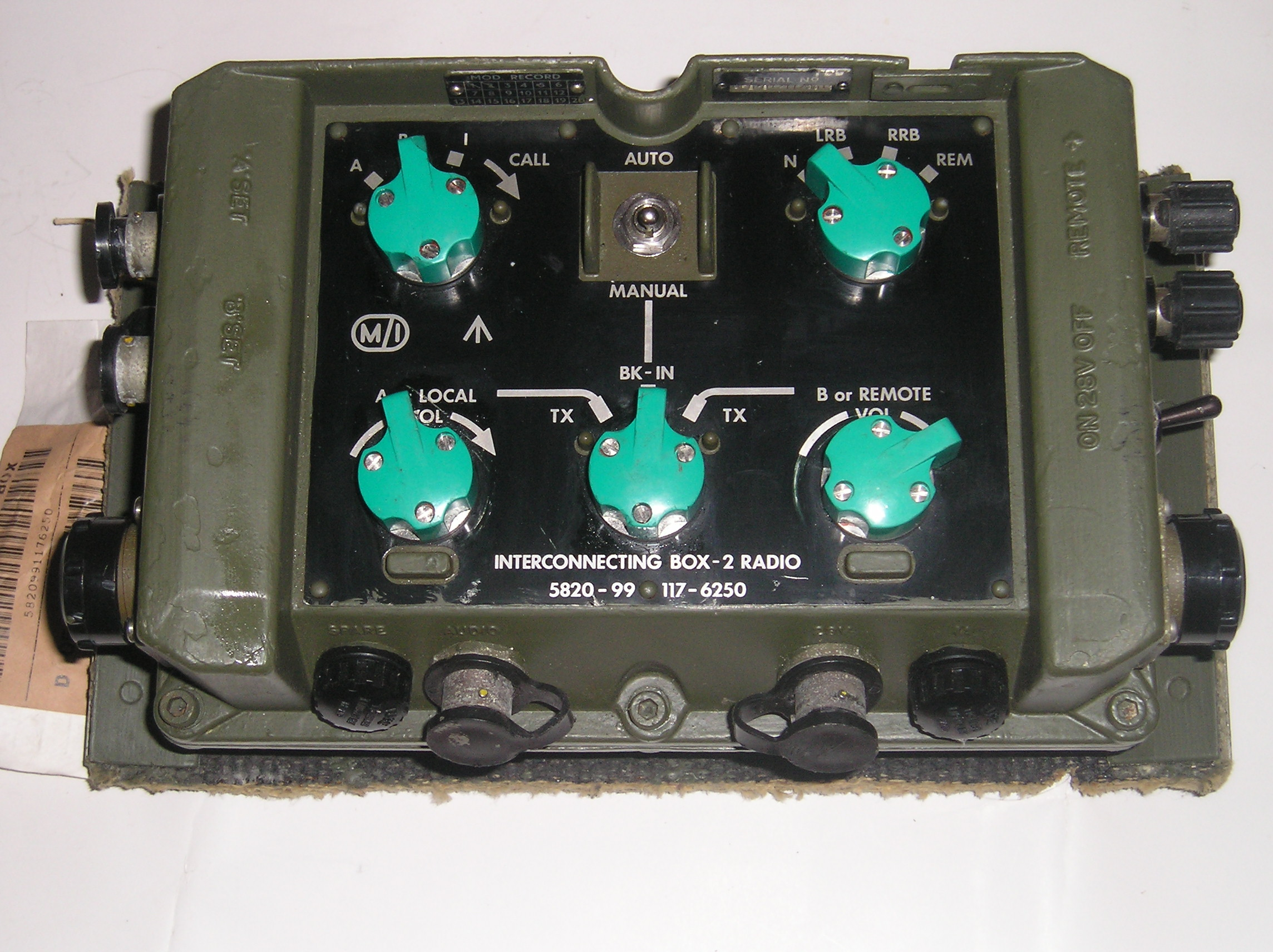
For simple installations where there are only two main radios the IB2 box is probably the most effective method of control and interconnection. The IB2 allows the operator to access two sets from one control position and select either to monitor radio traffic.
The term “access” is used here rather than control. Settings such as frequency cannot be altered, either over the harness or remotely.
Rebroadcast between sets can be A-B or B-A as required. When working HF to VHF nets the local operator takes manual control, as the HF sets do not have automatic rebroadcast.
When two VHF sets are linked via the IB2 and their Remote Switches set to “AUTO “ incoming signals with the NATO 150Hz tone will trigger the transmit on the rebroadcast radio as selected on the IB2.
The local operator has the option to select break-in on either the A or B-side of the relay as desired but otherwise can leave the net unattended.
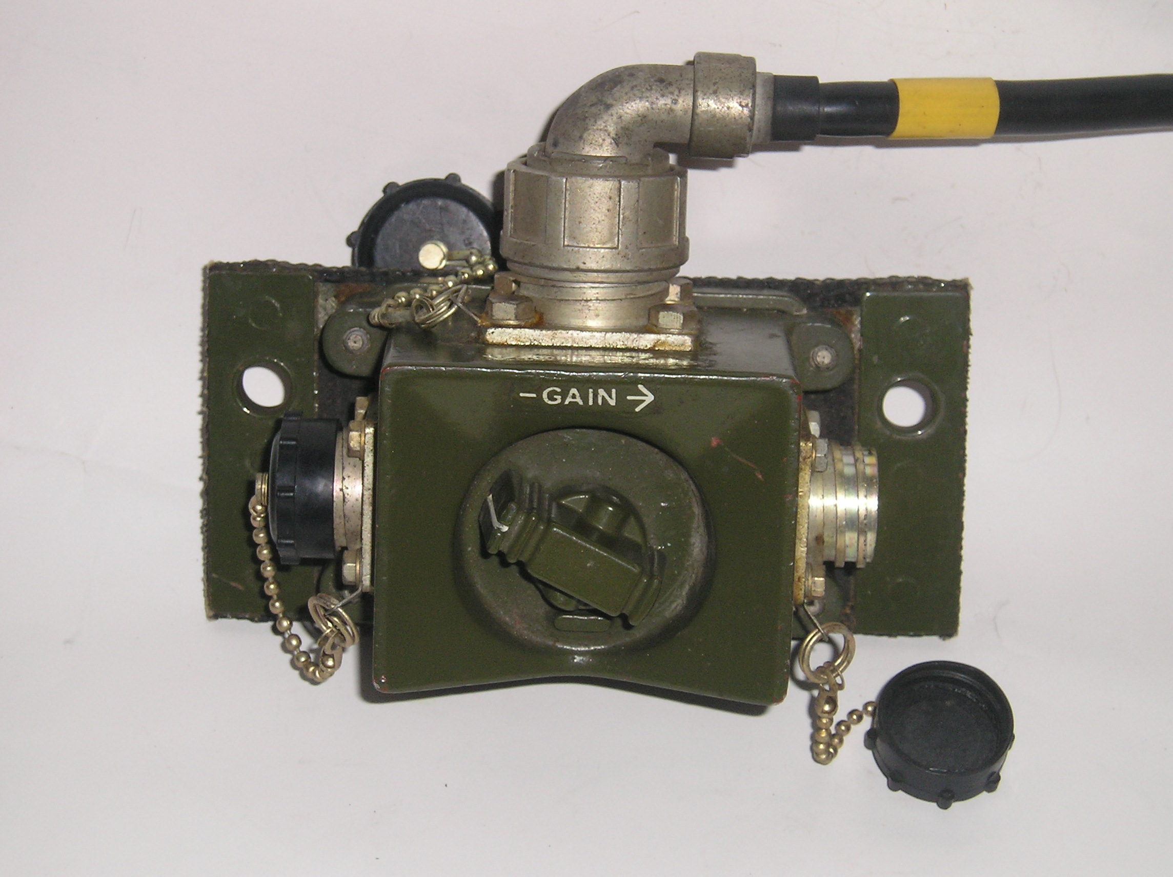
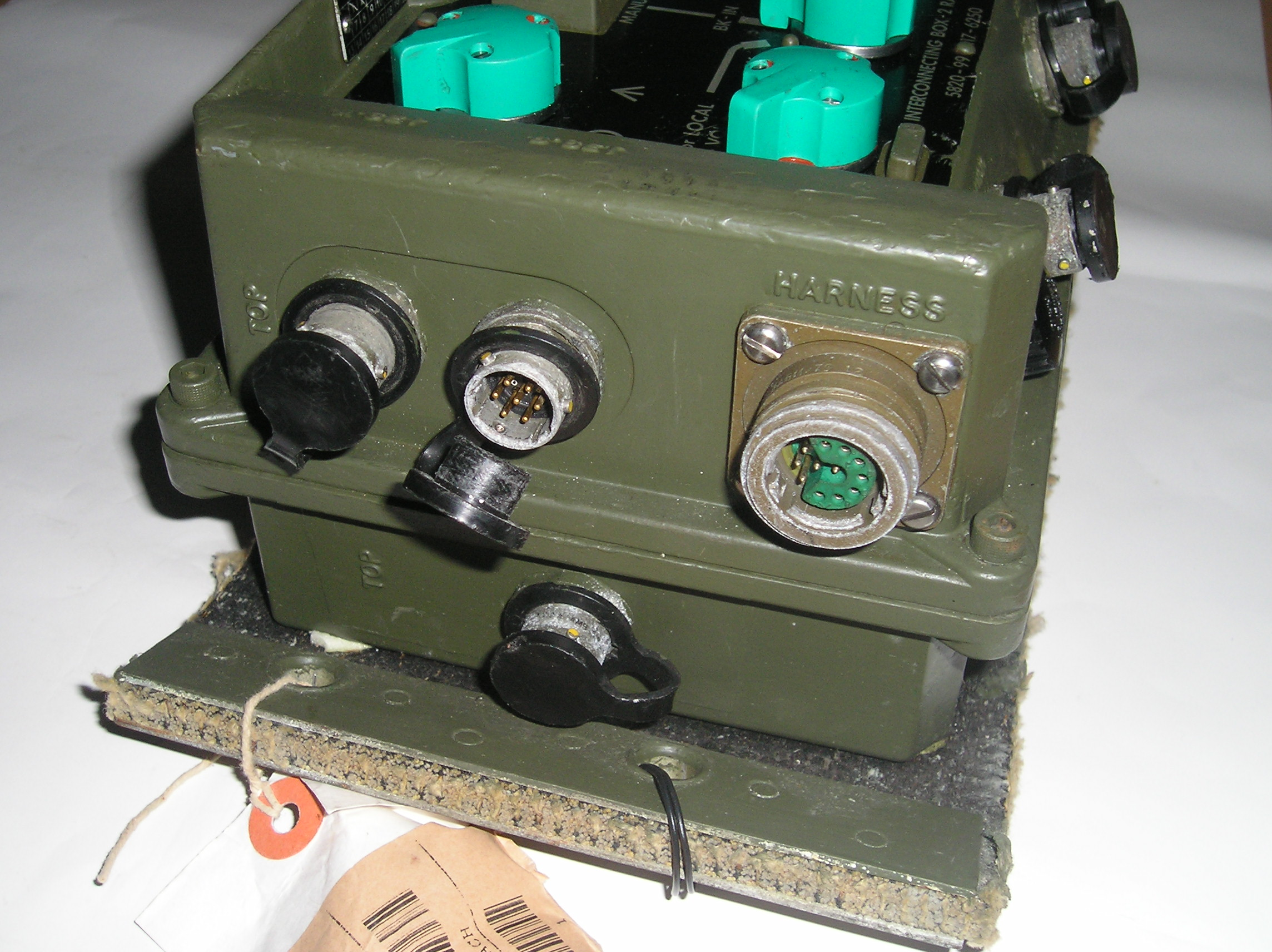
The IB2 unit contains active circuitry and accordingly requires a separate power cable from a fused outlet on the vehicles DC radio power distribution. Connections from the IB2 to radios A & B are made via 7 way control cables one to each set.
The main harness system boxes are linked together by 12 way connectors. This often takes the form of a Daisy Chain from one box to the next. On larger installations the boxes can be linked in a Ring Main, which increases the integrity of the connections.
If one section of the ring was damaged there is a good chance that continuity would be preserved by the other part and normal operation maintained.
In a typical small installation the only other box required might be a Loudspeaker amplifier. The 12w socket on the Amplifier Loudspeaker would be connected to the IB2 and the loudspeaker either connected to the 4mm “Banana Plug” terminals or 7 pin Audio plug as appropriate.

Clansman Power Supplies
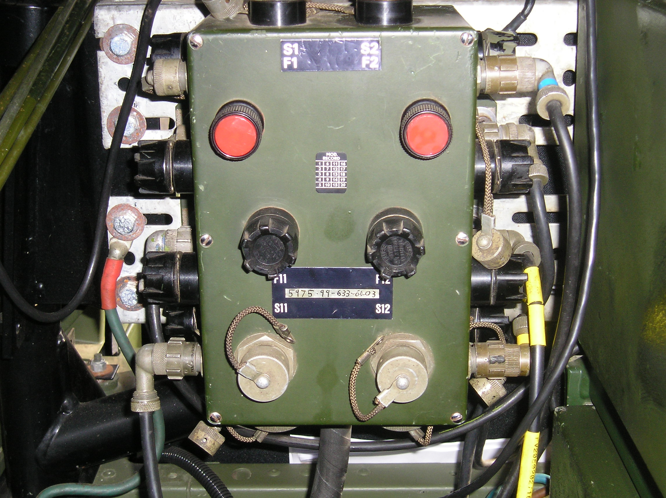
An important part of the Clansman system is the provision and distribution of battery power. Each piece of equipment is either provided with its own fused dc supply or powered from a common fused circuit. Following normal good practice the distribution fuses are principally intended to protect the connecting cables.

Units such as the IB2, Amplifier AF & DCCU also have fuses fitted that protect the individual units.
In FFR vehicles the radio system voltage is 24V provided from batteries that are separate from the vehicles electrics. GS vehicles usually have a 12V battery, which is common to vehicle and any radios fitted. In both cases these supplies are connected to a Fuse and Distribution unit. These have between one to fourteen outputs depending upon installation requirements. Simple GS installations may only have one fused output with a typical small installation having three. Larger installations will usually employ one or more 14-way units. These have eight standard 2-pin Clansman power outlets plus, four others and a pair of special Thorn 50 Amp sockets for powering an Amplifier RF 250W. When installed together with Tuner RF 250W this converts the RT321 to the High Power (300W pep) VRC322.
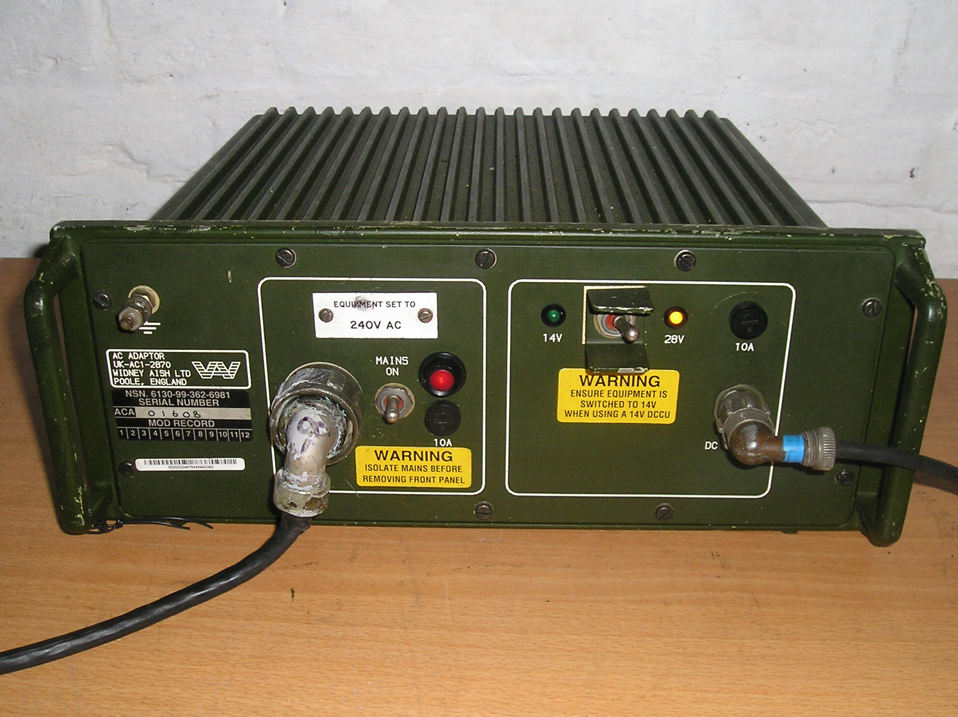
When Clansman radios are used as base stations it is often more convenient to operate these from a generator or AC mains supply. The AC Adaptor NSN 6130-99-362-6981 manufactured by Widney Aish in Poole Dorset provides 14/28V at about eight amps & is suitable for the lower powered radios. This will power the RT320, RT351, RT352 via DCCU and the RT321 directly. The RT353 may also be supplied but not on high power, which requires around 10 Amps. If the RT353 Tx power is switched to 15W or less there is no problem. The correct unit for supplying the RT353 & VRC322 station is PSU 50A, which is to be described later in this series of articles.
In the next instalment we look at the internal construction of Clansman sets with some general notes and a few pointers about repairs and the test equipment required.
Barry
G8DXU
Copyright 19.01.2014