
6th Instalment in the “From Larkspur to Clansman” series
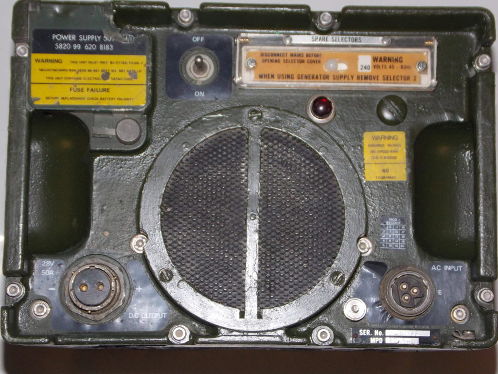
This instalment continues this series with an examination of the Power Supply Unit 50 Amp, NSN 5820-99-620-8183. This unit was designed to provide nominal 28V DC from the mains or generator for powering the VRC 322 HF installation or VRC353 VHF Transceiver. The VRC322 consisting of VRC321 HF Transceiver, Amplifier RF 250 Watt and Tuner RF 250 Watt. Selector RF also being used to improve selectivity in installations where there are other HF systems are in close proximity. These notes look at the general construction and operation, being intended as a guide to the areas that may require attention, rather than a definitive guide to repair.
PSU 50A General construction
In common with the entire Clansman series equipment the PSU 50A is of very robust construction. It is suitable for installation in vehicles dropped by parachute or transportation without additional packing. The circuitry is contained within a sturdy die-cast aluminium housing, which is sealed with a gasket at the front panel. This should be smeared with general-purpose grease upon re-assembly. Weighing in at 40kg the PSU 50A supplies up to 53 Amps at between 25-30V and is suitable for continuous operation at full load. PSU 50A is normally used to float charge vehicle batteries, which directly power the station radio. Whilst the supply is capable of operation in wet or dusty environments care should be taken to prevent undue water ingress to the fan grill. Unlike most other Clansman equipment this unit is not hermetically sealed. This is due to the front fan air-intake and rear filter orifice not being isolated from the supplies internal components. Simple foam plastic filters being fitted behind the front and rear grills. Whilst these remove the majority of larger dust particles they were severely tested under the battlefield conditions in theatres such as Afghanistan. The fine sand in these regions penetrated the internal areas of the case and circuitry. Considerable amounts of sand were found within some supplies examined after return from areas such as Kabul. There is however little evidence of this actually causing failures, which is probably mainly due to the very dry conditions.
Outline principle of operation
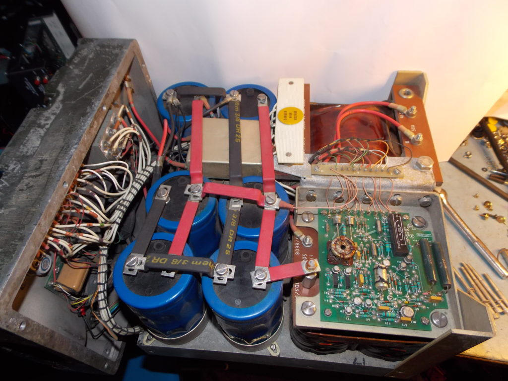
Mains input is passed through a Hydraulic Over-current Circuit Breaker and voltage selector panel to a conventional Iron cored transformer. An oscillator running at 20 kHz provides pulses, which switch a pair of Tyhristors on each half cycle and control the mains power input to the transformer primary winding. The AC output from the transformer is applied to a conventional bridge rectifier. This is passed through a choke and smoothed by a bank of six electrolytic capacitors totalling 198,000uF. DC Output is routed through the primary winding on a Ferrite Torroid forming a Magnetic Amplifier (1CT1). The 20 KHz oscillator providing initial timing for the Thyristor driver is fed through this secondary winding. The impedance of this winding changes with primary current, forming a feedback loop to control maximum available load current. Output voltage is also compared with a stable reference to produce a control signal, which alters the firing angle of the Thyristors. This method is more efficient than conventional series regulation circuits. An 80A fuse is placed in series with the final output before final connection to the output socket. There is a diode across the supply that will blow this fuse should the battery connection be reversed.
Preventative Maintenance
The front panel is retained to the case by eight 5mm Hexagonal Key bolts. Three bolts on the underside of the case retain the main chassis to the case and must also be removed. There are also three threaded stabilizing screws fitted within the under-chassis retaining bolt locations. These need to be loosened before the main chassis is finally withdrawn. Do not try to remove the two rear screws, one on each side of the rear grill; these retain an internal secondary screen, which does not normally need to be disturbed.
Routine Servicing
One important area of attention is to ensure that internal nuts and bolts are tight and have not worked loose. Check the tightness of all visible nuts and bolts. The screws on each of the six main electrolytic capacitors that retain their connecting straps and tags require particular attention.
Electrical Safety
Persons undertaking the testing and servicing of this equipment should ensure that they are familiar with the basic principles of electrical safety. Mains voltages are exposed when the PSU 50A is powered with the case removed. Particular areas of attention being the Mains input connector, Circuit breaker, Mains transformer input tags and Thyristor connections around the Driver PEC. If you are unsure of the correct procedures to adopt then seek guidance from a suitably qualified engineer. Applying Mains Power Ensure that the mains input connector is disconnected from the mains and removed from the socket on the front of the unit. Check that the correct mains voltage settings have been set on the front panel selector. The voltage currently selected should be shown in the middle of the Perspex cover plate. Raise this cover by loosening the two screws and hinging it forwards. There are seven screws, which are located according to the voltage being selected.
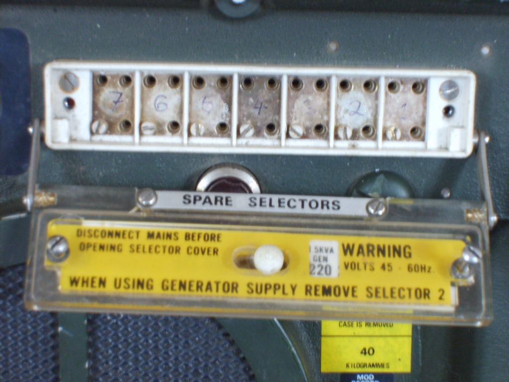
After checking that the selection is correct, ensure that each of the selector screws are tight. The cover plate can now be replaced. Note that the right hand screw retaining this cover operates a Microswitch. This is a safety feature that removes mains power from the selector panel when the cover is raised. It should not be relied upon and the mains supply should always be disconnected before making any such adjustments. The mains input connector should be located to the front panel socket before the lead is connected to the mains. This is because it is possible to accidentally cross connect the mains input socket during rotation to correctly locate the shell. Operating the toggle of the circuit breaker should start the PSU 50A and the front panel fan. After a delay of 3-10 seconds, which allows the regulator circuit to stabilize, DC output of 26.75-29.25V should be available at the 2 pin socket. The Red indicator lamp should illuminate. These bulbs used are 12V 100mA T1 ¾ (5mm) size Midget Flange mounting. They often fail on PSUs that have seen long service and are easily replaced by unscrewing the lamp cap. Replacement filament lamps are available from Farnell under Order code 1139340.
Common Faults
In faulty supplies the circuit breaker will often trip upon operation of the toggle due to excess current being drawn by the unit. This breaker has three windings one 12A for the nominal 240V mains input and the second 20A for 115-120V operation. The third 20A winding is in the negative line, being common to all input voltages. The hydraulic nature of the breaker prevents tripping on supply transients. Disconnect the mains connection and remove the case as previously described before carrying out any inspections, tests or repairs on these units.
Driver PEC R17 / R18
Resistors R17 and R18 on the driver PEC are associated with the gate circuitry of the two Thyristors CSR1 & CSR2. These Thyristors perform the power control function in the mains transformer primary circuit. In all units examined, R17 and R18 were either burnt out or have seriously changed in resistance value. They should be 82 Ohms and replacement with 2W Metal Oxide types is advised. Farnell Order code 1565493 items being suitable. These resistors are effectively in parallel and on good units; approximately 41 Ohms will be measured when checking across each item in circuit. Replacement of R17 & 18 Remove the three screws that retain the Thyristor cover and associated threaded pillars. Next remove the 4 screws and associated washers that retain the PEC to the chassis. The easiest way to lift the Driver PEC without un-soldering connections is to remove the stud nut on each Thyristor and their two connecting tags. Note the positions of the connecting tags and retain the Nuts, Washers, Stud Insulators and Mica Washers from CSR1 & CSR2 for reassembly. Lift the PEC together with the Thyristors, Gate and Anode connections. R17 & 18 can now be replaced. C1 & C2 should also be checked at this time and replaced if required. (See “Other causes of problems”) Clean away the old and probably dry, Silicon Thermal conductive grease around each Thyristor. Apply new conductive grease to each device and mica washer before assembly. Reconnect the Thyristor Anode and Cathode connections; re-fit PEC retaining screws, pillars and insulating cover.
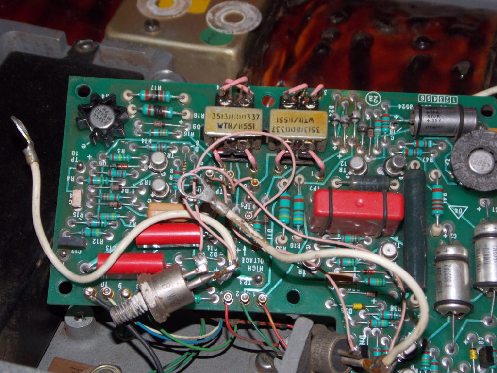
Should any of the Thyristor connections to the PEC be damaged or broken they should be reconnected as follows:- Driver Board Pin Connection 2a 4 2CSR1 Gate 2a 5 2CSR1 Cathode & 2CSR2 Anode (OUTPUT SIDE) 2a 6 2CSR1 Anode & 2CSR2 Cathode (INPUT SIDE) 2a 7 2SCR2 Gate
Other causes of problems
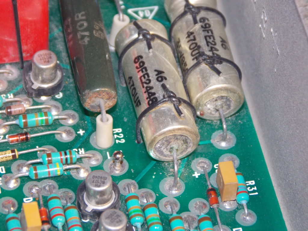
On some units that have been subjected to vibration either in vehicles or during transport, connections have failed. One area identified that has caused failures is on the Drive PEC. The welds on Tantalum Capacitors C1 & C2 body (negative end) have broken away. Replacement of C1 & C2 is therefore required. Wet Tantalum capacitors are very expensive and for amateur service, replacement with ordinary 85 deg C electrolytic capacitors is suggested. Suitable 470uF, 40V, 85C types are available from Farnell under order code 1165389.
Fan Filter replacement
The front and rear filter covers can be removed by rotating the three fasteners one-half turn. In most units examined the existing filters were in very poor condition. The fan blades, grills and surrounding areas should be cleaned as required. Replacement filters can be fabricated out of 4mm thick foam plastic cut to a diameter of about 114mm.
Repainting
Colour. Deep Bronze Gree
Acrylic
Original paint is usually a two pack isocyanate type. However the above is entirely suitable for touching up small areas to improve the cosmetic appearance.
Conclusion
Once the routine servicing measures outlined above have been applied PSU 50A units should continue to give reliable service. Whilst heavy these supplies are capable of continuous operation at full load. They are well screened and do not generally cause any significant interference at HF or VHF. Notes Crinkle washers used in this equipment may contain Beryllium. These are safe to handle but should not be damaged or filed. Avoid breathing any dust from within the equipment. REME = Radio Electrical and Mechanical Engineers.
Substitute components and their suppliers are suggestions only; no recommendation is made as to suitability for purpose.
This post is currently being updated. More photographs and information will be added shortly
Copyright G8DXU 2019