
Part 7 in the series “From Larkspur to Clansman” by G8DXU
Having acquired a large quantity of non working IBMUs the following outlines the author’s experiences in carrying out basic repairs on these units. The excellent article in VMARS signal by Collin Guy describes the general operation and physical construction of this equipment. For those that are not VMARS members some operational details will be provided here.
With most equipment that may have unknown faults it is always good practice to connect the unit under test to a laboratory bench power supply with current limiting. For testing purposes the supply voltage should be set at 24V with an initial current limit of about 600mA. When switched on, correctly functioning units will draw an initial surge current whilst capacitors charge and then settle to a quiescent current of around 46mA.
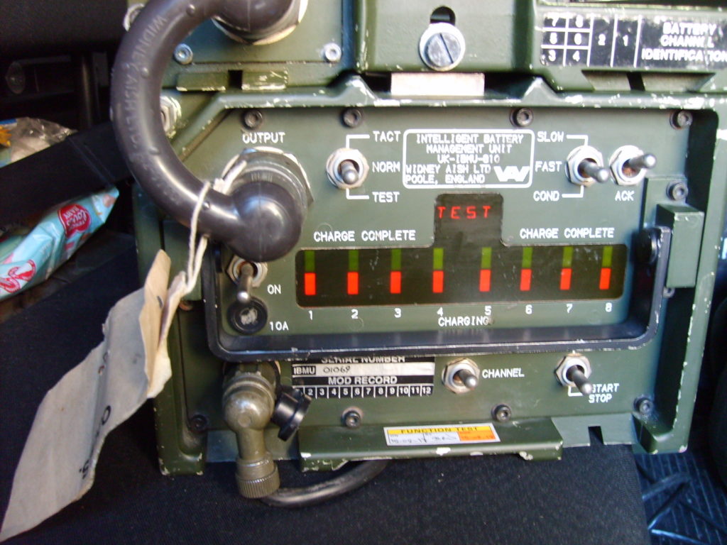
The first IBMU examined was switched on and the top line of the LED display showed VLO. This indicates a low voltage input or failure of one or more of the internal power rails.
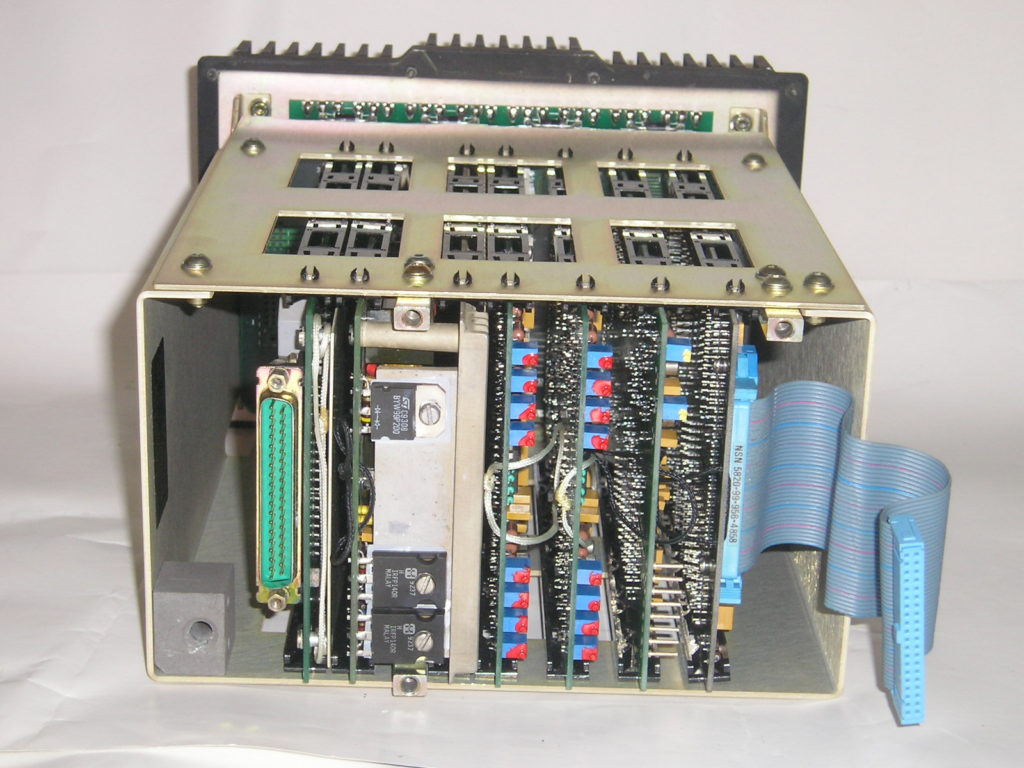
Dismantling the unit for service.
Disconnect the 2-pin power input connector and cable linking between output and battery tray.
To access the internal boards remove the front panel Hex screws. Carefully hinge the front panel away from the main case, taking care not to damage the flexible printed connector on the left hand side. Unclip the 40-way ribbon cable connecting the front panel to the Logic Module. Now remove the three hex bolts holding the plate that retains the cards in position. Remove this plate and store with the bolts for later refitting.
The 40-way ribbon cable can now be reconnected whilst some voltage checks are performed.
Connect the power input to the current limited supply and switch the IBMU on. Using a voltmeter with reference to chassis ground, check the voltages at the pins on the front of the Analogue module.
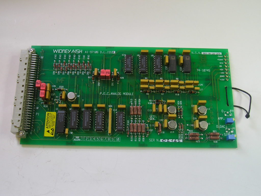
Analogue Card
Voltages on the test-points appearing on the front of the Analogue module.
Looking at the front of the card the various test points are as shown.
- + 15V
- A GND (Voltmeter Negative connection)
- – 15V
- + 5V
- VR
- VCN
- + 5V
- – 5V
Voltages on fully working units should be close to those indicated but on faulty units one or more will be found to be low or nil. When incorrect, low or high voltages are found, the first place to look for faults is on the Power Supply Unit Card. This requires the power card to be withdrawn from the frame for further investigations.
Electrostatic Precautions
All individual cards are provided with a cord at the front, which should be used to withdraw the card from the card frame. To reduce the possibility of damage to the semiconductors by Electro Static Discharge (ESD), precautions should be taken.
This normally entails the wearing of a proprietary conductive wristband and cord together with the use of conductive matting on the workbench. Cards that are withdrawn awaiting repair should be handled and stored in conductive plastic bags.
Card Module Numbering
For testing purposes and Built In Test Equipment (BITE) reports, Cards or Modules are numbered from Right to Left looking at the front of the IBMU. Thus the Power Card is MODULE 5. Faults are reported on the LED display using these numbers.
Power Supply Card – Module 5
Fortunately the power supply is largely an independent unit that can be tested as a separate entity. Once the card has been placed on the bench and taking the usual electrostatic precautions as above, the heat-sink needs to be removed. Unscrew the bolts holding the power transistor tabs and remove the screws retaining the PCB to the heat-sink. Ensure that the mica and silicone insulators for the transistors are safely kept for correct reassembly.
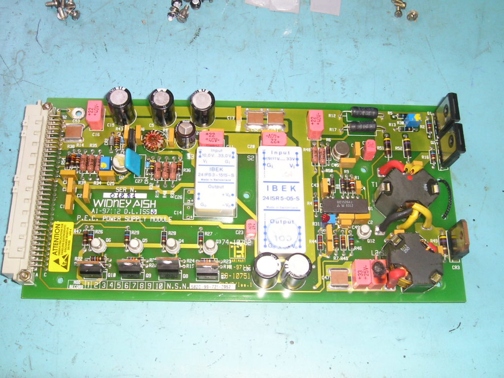
Once the heat-sink has been removed carefully examine the components for any obvious signs of damage or overheating. The main cause of failure in these units is usually due to faulty Tantalum capacitors, these often fail short circuit.
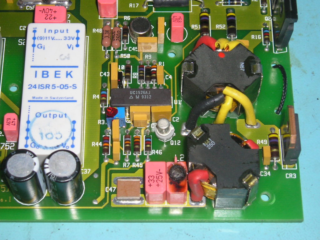
The photograph shows one such capacitor (C40, Pink, EuroTant) approximately bottom centre. This has actually burnt out and is typical of such catastrophic failure in power applications. All Tantalum capacitors in the IBMU should be treated as suspect! And it is therefore suggested that these are changed for new items. The following is a complete list of Tantalum capacitors in the PSU Card: –
| Capacitor | Specification |
| C11, C16, C20, C38 | 22uF 40V |
| C23 | 47uF 6.3V |
| C14, C26 | 22uF 16V |
| C39 | 6.3uF 40V |
| C40, C54 | 33uF 25V |
| C3 | 4u7 |
If desired only the faulty capacitors need to be replaced. It is however strongly recommended that all of the above capacitors are changed for new Tantalum items. The ESR of Tantalum capacitors is lower than electrolytic types, however 22uF 40V Tantalums are quite expensive (approx £13 each). Given the only slight degradation in performance and for amateur use, it is probably expedient to replace these with electrolytic types.
The following list of part numbers from Farnell Electronic Components gives suitable replacements.
CAPACITOR 10uF 50V 881-2594
CAPACITOR 22uF 63V 881-2640
CAPACITOR 33uF 25V 110-0482
CAPACITOR TANT 22uF 110-0470
The above components are suggestions only and not an endorsement of any particular manufacturer or supplier.
The PSU printed board has plated through hole connections and components should only be removed by the use of a good vacuum de-soldering station. Hand solder pumps are unlikely to have sufficient suction to remove parts without damage to the delicate lands and tracks.
Capacitors should be tested with a capacitance meter or component analyser. Such as the Tinsley Prism Databridge
Short circuit items are more easily located by using a Tone Ohm made by Polar Instruments or similar circuit resistance tracer. For those not familiar with the Tone Ohm, these identify resistance deviations by change in tone from a voltage-controlled oscillator. There is also a digital display indicating resistance, voltage or current at the point of test. These units are brilliant for locating faults with shorts or disconnections on printed boards.
With a Capacitance meter, check the capacitance of C40 & C54 in circuit. This should read approximately 290uF due to 220uF + 33uF + 33uF in parallel and should not be substantially lower than 286uF -10%
Notes
LED Display codes
CAP = CAPACITY
DCHG = DISCHARGING
CALC = CALCULATING
VLO = VOLTAGE LOW (DC Input Low <21V or internal fault)
VHI = VOLTAGE HIGH (DC Input >32V)
TEMP = Power Interface failure (Temperature on Heat-sink >90C)
MOD1 = MODULE 1 Fail (Logic Module)
MOD2 = MODULE 2 Fail (Analogue Module)
MOD3 = MODULE 3 Fail (Driver 1 Module, battery charge channels 1-4)
MOD4 = MODULE 4 Fail (Driver 2 Module, battery charge channels 5-8)
MOD5 = MODULE 5 Fail (PSU Module)
MOD6 = MODULE 6 Fail (Control & Display Module) Front Panel/Switch)
Software Versions
SW181 Iss 1.31 U2 Date 11.03.94
SW220 Iss 1.06 U2 Date 16.02.98
IBMU manufactured by Widney Aish, Poole, Dorset.
Later units marked, Charge Electronic Design, Poole. Dorset.